This filter is found in the image window menu under
Filters->Map->Warp.
This filter has no Preview.
This filter displaces pixels of active layer or selection according to
grey levels of a Displacement map. Pixels are
displaced according to the gradient slope in the displacement map.
Pixels corresponding to solid areas are not displaced; the higher the
slope, the higher the displacement.
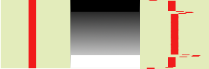
Figure 11.172.
From left to right: original image, displace map, displaced image
Solid areas of displacement map lead to no displacement. Abrupt
transitions give an important displacement. A linear gradient
gives a regular displacement. Displacement direction is
perpendicular to gradient direction (angle = 90°)
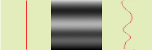
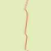
Figure 11.173.
With a non-linear gradient
A non-linear gradient leads to curls.
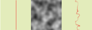
Figure 11.174.
With a complex gradient:
And a complex gradient, such as the
Solid Noise filter can
create, gives a swirl effect.
This filter offers the possibility of masking a part of the image to
protect it against filter action.
12.11.2.
Options
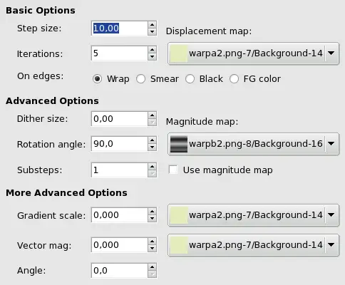
Figure 11.175.
Warp filter options
Basic Options
Step Size
“Step” is displacement distance for every filter
iteration. A 10 value is necessary to get a one pixel
displacement. This value can be negative to invert
displacement direction.
Iterations
Iteration is the number of repetitions of
effect when applying filter.
On Edges
Because of displacement, a part of pixels are driven over the
borders of layer or selection, and, on the opposite side,
pixels places are emptying. Four following options allow you
to fix this issue:
Warp (default): What goes out on
one side is going into the opposite side.
Smear: Emptying places are filled
with a spreading of the neighbouring image line.
Black: Emptying places are filled
with black color.
FG Color: Emptying places are filled
with the Foreground color of the color area in Toolbox.
Displacement Map
To be listed in this drop-down list, the displacement map,
which is a grey-scaled image, must be present on
your screen when you call filter and must have the same size
as the original image.
be
Advanced Options
Dither Size
Once all pixels displaced, this option scatters them randomly,
giving grain to the image. The higher this value (0.00-1.00),
the thinner the grain.
Figure 11.176.
With a 3.00 dither size:
Rotation Angle
This option sets displacement angle of pixels according to the
slope direction of gradient. Previous examples have been
created with a vertical gradient and a 90° angle: so,
pixels were displaced horizontally and nothing went out of the
image borders. Here is an example with a 10° angle and 6
iterations:
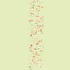
Figure 11.177.
With a 10° angle and 6 iterations:
Displacement is made according to a 10° angle against
vertical. Pixels going out the lower border on every
iteration are going into through the upper border
(Wrap option checked), giving a dotted line.
Magnitude map
In addition to displacement map, you can add a
Magnitude Map. This map is also a
grey-scaled image, with the same size as the source image and
which must be present on your screen when you call filter.
This map gives more or less strength to filter on some parts
of the image, according to the grey levels of this magnitude
map. Image areas corresponding to white parts of this map will
undergo all the strength of filter. Image areas corresponding
to black parts of the map will be spared by filter.
Intermediate grey levels will lessen filter action on
corresponding areas of the image. Use magnitude
map must be checked for that.
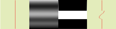
Figure 11.178.
Magnitude Map example:
From left to right: original image, displacement map,
magnitude map, after applying “Warp” filter.
You can see that the black areas of magnitude map prevent
filter to take action.
Published under the terms of the GNU General Public License