After installing Red Hat Enterprise Linux, set up the cluster hardware components and
verify the installation to ensure that the nodes recognize all
the connected devices. Note that the exact steps for setting up the
hardware depend on the type of configuration. Refer to Section 2.1 Choosing a Hardware Configuration for more information about cluster
configurations.
To set up the cluster hardware, follow these steps:
Shut down the nodes and disconnect them from their
power source.
In addition, it is recommended to connect each power switch (or
each node's power cord if not using power switches) to a different
UPS system. Refer to Section 2.5.3 Configuring UPS Systems for
information about using optional UPS systems.
Set up shared disk storage according to the vendor instructions
and connect the nodes to the external storage enclosure. Refer to
Section 2.3.2 Shared Storage considerations.
In addition, it is recommended to connect the storage enclosure
to redundant UPS systems. Refer to Section 2.5.3 Configuring UPS Systems for more information about using
optional UPS systems.
Turn on power to the hardware, and boot each cluster
node. During the boot-up process, enter the BIOS utility to modify
the node setup, as follows:
Ensure that the SCSI identification number used by the host bus adapter
is unique for the SCSI bus it is attached to. Refer to Section A.3.4 SCSI Identification Numbers for more information about performing
this task.
Enable or disable the onboard termination for each host bus
adapter, as required by the storage configuration. Refer to
Section A.3.2 SCSI Bus Termination for more information about
performing this task.
Enable the node to automatically boot when it is
powered on.
Exit from the BIOS utility, and continue to boot each
node. Examine the startup messages to verify that the Red Hat Enterprise Linux
kernel has been configured and can recognize the full set of shared
disks. Use the dmesg command to display console
startup messages. Refer to Section 2.4.3 Displaying Console Startup Messages
for more information about using the dmesg
command.
Ethernet channel bonding in a no-single-point-of-failure cluster
system allows for a fault tolerant network connection by combining two
Ethernet devices into one virtual device. The resulting channel bonded
interface ensures that in the event that one Ethernet device fails, the
other device will become active. This type of channel bonding, called an
active-backup policy allows connection of both
bonded devices to one switch or can allow each Ethernet device to be
connected to separate hubs or switches, which eliminates the
single point of failure in the network hub/switch.
Channel bonding requires each cluster node to have two Ethernet
devices installed. When it is loaded, the bonding module uses the MAC
address of the first enslaved network device and assigns that MAC
address to the other network device if the first device fails link
detection.
To configure two network devices for channel bonding, perform the
following:
Create a bonding devices in
/etc/modprobe.conf. For example:
alias bond0 bonding
options bonding miimon=100 mode=1
This loads the bonding device with the
bond0 interface name, as well as
passes options to the bonding driver to configure it as an
active-backup master device for the enslaved network interfaces.
Edit the
/etc/sysconfig/network-scripts/ifcfg-ethX
configuration file for both eth0 and eth1 so that the files show
identical contents. For example:
This will enslave ethX
(replace X with the assigned number of
the Ethernet devices) to the bond0 master device.
Create a network script for the bonding device (for example,
/etc/sysconfig/network-scripts/ifcfg-bond0),
which would appear like the following example:
Fence devices enable a node to power-cycle another node before
restarting its services as part of the failover process. The ability
to remotely disable a node ensures data integrity is maintained under
any failure condition. Deploying a cluster in a production environment
requires the use of a fence device. Only
development (test) environments should use a configuration without a
fence device. Refer to Section 2.1.2 Choosing the Type of Fence Device for a
description of the various types of power switches.
In a cluster configuration that uses fence devices such as power
switches, each node is connected to a switch through either a serial
port (for two-node clusters) or network connection (for multi-node
clusters). When failover occurs, a node can use this connection to
power-cycle another node before restarting its services.
Fence devices protect against data corruption if an unresponsive
(or hanging) node becomes responsive after its services have failed
over, and issues I/O to a disk that is also receiving I/O from another
node. In addition, if CMAN detects node failure, the failed node will
be removed from the cluster. If a fence device is not used in the
cluster, then a failed node may result in cluster services being run
on more than one node, which can cause data corruption and possibly
system crashes.
A node may appear to hang for a few seconds
if it is swapping or has a high system workload. For this reason,
adequate time is allowed prior to concluding that a node has
failed.
If a node fails, and a fence device is used in the cluster, the
fencing daemon power-cycles the hung node before restarting its
services. This causes the hung node to
reboot in a clean state and prevent it from issuing I/O and corrupting
cluster service data.
When used, fence devices must be set up according to the vendor
instructions; however, some cluster-specific tasks may be required to
use them in a cluster. Consult the manufacturer documentation on
configuring the fence device. Note that the cluster-specific
information provided in this manual supersedes the vendor
information.
When cabling a physical fence device such as a power switch, take
special care to ensure that each cable is plugged into the appropriate
port and configured correctly. This is crucial because there is no
independent means for the software to verify correct cabling. Failure
to cable correctly can lead to an incorrect node being power cycled,
fenced off from shared storage via fabric-level fencing, or for a node
to inappropriately conclude that it has successfully power cycled a
failed node.
Uninterruptible power supplies (UPS) provide a highly-available
source of power. Ideally, a redundant solution should be used that
incorporates multiple UPS systems (one per server). For maximal
fault-tolerance, it is possible to incorporate two UPS systems per
server as well as APC Automatic Transfer Switches to manage the power
and shutdown management of the server. Both solutions are solely
dependent on the level of availability desired.
It is not recommended to use a single UPS infrastructure as the
sole source of power for the cluster. A UPS solution dedicated to the
cluster is more flexible in terms of manageability and
availability.
A complete UPS system must be able to provide adequate voltage and
current for a prolonged period of time. While there is no single UPS
to fit every power requirement, a solution can be tailored to fit a
particular configuration.
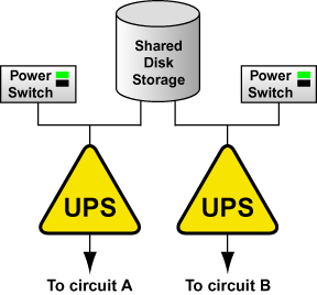
If the cluster disk storage subsystem has two power supplies with
separate power cords, set up two UPS systems, and connect one power
switch (or one node's power cord if not using power
switches) and one of the storage subsystem's power cords to each UPS
system. A redundant UPS system configuration is shown in Figure 2-2.
Figure 2-2. Redundant UPS System Configuration
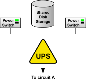
An alternative redundant power configuration is to connect the
power switches (or the nodes' power cords) and the disk storage
subsystem to the same UPS system. This is the most cost-effective
configuration, and provides some protection against power
failure. However, if a power outage occurs, the single UPS system
becomes a possible single point of failure. In addition, one UPS
system may not be able to provide enough power to all the attached
devices for an adequate amount of time. A single UPS system
configuration is shown in Figure 2-3.
Figure 2-3. Single UPS System Configuration
Many vendor-supplied UPS systems include Red Hat Enterprise Linux applications that
monitor the operational status of the UPS system through a serial port
connection. If the battery power is low, the monitoring software
initiates a clean system shutdown. As this occurs, the cluster
software is properly stopped, because it is controlled by a SysV
runlevel script (for example,
/etc/rc.d/init.d/rgmanager).
Refer to the UPS documentation supplied by the vendor for detailed
installation information.
After shared disk storage has been set up, partition the disks
so they can be used in the cluster. Then, create file systems or raw
devices on the partitions.
Use parted to modify a disk partition table
and divide the disk into partitions. While in
parted, use the p to display
the partition table and the mkpart command to
create new partitions. The following example shows how to use
parted to create a partition on disk:
Invoke parted from the shell
using the command parted and specifying an
available shared disk device. At the (parted)
prompt, use the p to display the current
partition table. The output should be similar to the
following:
Disk geometry for /dev/sda: 0.000-4340.294 megabytes
Disk label type: msdos
Minor    Start       End     Type      Filesystem  Flags
Decide on how large of a partition is
required. Create a partition of this size using the
mkpart command in
parted. Although the
mkpart does not create a file system, it
normally requires a file system type at partition creation
time. parted uses a range on the disk to
determine partition size; the size is the space between the end
and the beginning of the given range. The following example
shows how to create two partitions of 20 MB each on an empty
disk.
(parted) mkpart primary ext3 0 20
(parted) mkpart primary ext3 20 40
(parted) p
Disk geometry for /dev/sda: 0.000-4340.294 megabytes
Disk label type: msdos
Minor    Start       End     Type      Filesystem  Flags
1          0.030     21.342  primary
2         21.343     38.417  primary
When more than four partitions are required on a
single disk, it is necessary to create an extended
partition. If an extended partition is required, the
mkpart also performs this task. In this case, it
is not necessary to specify a file system type.
Note
Only one extended partition may be created, and the
extended partition must be one of the four
primary partitions.
(parted) mkpart extended 40 2000
(parted) p
Disk geometry for /dev/sda: 0.000-4340.294 megabytes
Disk label type: msdos
Minor    Start       End     Type      Filesystem  Flags
1          0.030     21.342  primary
2         21.343     38.417  primary
3         38.417   2001.952  extended
An extended partition allows the creation of
logical partitionsinside of it. The following
example shows the division of the extended partition into two
logical partitions.
(parted) mkpart logical ext3 40 1000
(parted) p
Disk geometry for /dev/sda: 0.000-4340.294 megabytes
Disk label type: msdos
Minor    Start       End     Type      Filesystem  Flags
1          0.030     21.342  primary
2         21.343     38.417  primary
3         38.417   2001.952  extended
5         38.447    998.841  logical
(parted) mkpart logical ext3 1000 2000
(parted) p
Disk geometry for /dev/sda: 0.000-4340.294 megabytes
Disk label type: msdos
Minor    Start       End     Type      Filesystem  Flags
1          0.030     21.342  primary
2         21.343     38.417  primary
3         38.417   2001.952  extended
5         38.447    998.841  logical
6        998.872   2001.952  logical
A partition may be removed using
parted's rm command. For
example:
(parted) rm 1
(parted) p
Disk geometry for /dev/sda: 0.000-4340.294 megabytes
Disk label type: msdos
Minor    Start       End     Type      Filesystem  Flags
2         21.343     38.417  primary
3         38.417   2001.952  extended
5         38.447    998.841  logical
6        998.872   2001.952  logical
After all required partitions have been created,
exit parted using the quit
command. If a partition was added, removed, or changed while
both nodes are powered on and connected to the shared storage,
reboot the other node for it to recognize the
modifications. After partitioning a disk, format the partition
for use in the cluster. For example, create the file systems for
shared partitions. Refer to Section 2.5.3.2 Creating File Systems for more information on
configuring file systems.
For basic information on
partitioning hard disks at installation time, refer to the
Red Hat Enterprise Linux Installation Guide.
Use the mkfs command to create an ext3 file
system. For example:
mke2fs -j -b 4096 /dev/sde3
For optimal performance of shared file systems, make sure to
specify a 4 KB block size with the mke2fs -b
command. A smaller block size can cause long fsck
times.