The Red Hat Cluster Manager allows administrators to use
commodity hardware to set up a cluster configuration that meets the
performance, availability, and data integrity needs of applications and
users. Cluster hardware ranges from low-cost minimum configurations that
include only the components required for cluster operation, to high-end
configurations that include redundant Ethernet channels, hardware RAID,
and power switches.
Regardless of configuration, the use of high-quality hardware in a
cluster is recommended, as hardware malfunction is a primary cause of
system down time.
Although all cluster configurations provide availability, some
configurations protect against every single point of
failure. In addition, all cluster configurations provide
data integrity, but some configurations protect data under every failure
condition. Therefore, administrators must fully understand the needs of
their computing environment and also the availability and data integrity
features of different hardware configurations to choose the cluster
hardware that meets the proper requirements.
A minimum hardware configuration includes
only the hardware components that are required for cluster operation, as
follows:
At least two servers to run cluster services
Ethernet connection for sending heartbeat pings and for client network
access
Network Switch to connect cluster nodes and resources
A fence device
The hardware components described in Table 2-1 can be used to set up a minimum
cluster configuration. This configuration does not guarantee data
integrity under all failure conditions, because it does not include
power switches. Note that this is a sample configuration; it is
possible to set up a minimum configuration using other
hardware.
 | Warning |
|---|
| | The minimum cluster configuration is not a supported solution
and should not be used in a production
environment, as it does not guarantee data integrity under all
failure conditions. |
| Hardware | Description |
|---|
| At least two server systems | Each system becomes a node exclusively for use in the
cluster; system hardware requirements are similar to that of
Red Hat Enterprise Linux 4. |
| One network interfaces for each node | One network interface connects to a hub or switch for
cluster connectivity. |
| One network cable with RJ45 connectors | Network cables connect to the network interface on each
node for client access and heartbeat packets. |
| RAID storage enclosure | The RAID storage enclosure contains one controller with
at least two host ports. |
| Two HD68 SCSI cables | Each cable connects one host bus adapter to one port on the RAID
controller, creating two single-initiator SCSI buses. |
Table 2-1. Example of Minimum Cluster Configuration
The minimum hardware configuration is a cost-effective cluster
configuration for development purposes; however, it contains
components that can cause service outages if failed. For example, if
the RAID controller fails, then all cluster services become
unavailable.
To improve availability, protect against component failure, and
guarantee data integrity under all failure conditions, the minimum
configuration is shown in Table 2-2.
| Problem | Solution |
|---|
| Disk failure | Hardware RAID to replicate data across multiple disks |
| RAID controller failure | Dual RAID controllers to provide redundant access to disk
data |
| Network interface failure | Ethernet channel bonding and failover |
| Power source failure | Redundant uninterruptible power supply (UPS) systems |
| Machine failure | Power switches |
Table 2-2. Improving Availability and Data Integrity
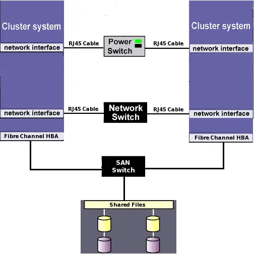
Figure 2-1 illustrates a hardware
configuration with improved availability. This configuration uses a
fence device (in this case, a network-attached power switch) and the
nodes are configured for Red Hat GFS storage attached to a Fibre Channel
SAN switch. For more information about configuring and using Red Hat GFS,
refer to the Red Hat GFS Administrator's Guide.
A hardware configuration that guarantees data integrity under
failure conditions can include the following components:
At least two servers to run cluster services
Switched Ethernet connection between each node for heartbeat
pings and for client network access
Dual-controller RAID array or redundant access to SAN or other
storage for shared partitions and service data
Power switches to enable each node to power-cycle
the other nodes during the failover process
Ethernet interfaces configured to use channel bonding
At least two UPS systems for a highly-available source of power
The components described in Table 2-3 can be
used to set up a no single point of failure cluster configuration that
includes two single-initiator SCSI buses and power switches to
guarantee data integrity under all failure conditions. Note that this
is a sample configuration; it is possible to set up a
no single point of failure configuration using other hardware.
| Hardware | Description |
|---|
| Two servers (up to 16 supported) | | Each node includes the
following hardware: | | Two network interfaces for: | | Client network access | | Fence device connection |
|
| One network switch | A network switch enables the connection of multiple nodes
to a network. |
| Three network cables (each node) | Two cables to connect each node to the redundant network
switches and a cable to connect to the fence device. |
| Two RJ45 to DB9 crossover cables | RJ45 to DB9 crossover cables connect a serial port on
each node to the Cyclades terminal server. |
| Two power switches | Power switches enable each node to power-cycle the other
node before restarting its services. Two RJ45 Ethernet cables
for a node are connected to each switch. |
| FlashDisk RAID Disk Array with dual controllers | Dual RAID controllers protect against disk and controller
failure. The RAID controllers provide simultaneous access to
all the logical units on the host ports. |
| Two HD68 SCSI cables | HD68 cables connect each host bus adapter to a RAID
enclosure "in" port, creating two single-initiator SCSI
buses. |
| Two terminators | Terminators connected to each "out" port on the RAID
enclosure terminate both single-initiator SCSI buses. |
| Redundant UPS Systems | UPS systems provide a highly-available source of
power. The power cables for the power switches and the RAID
enclosure are connected to two UPS systems. |
Table 2-3. Example of a No Single Point of Failure Configuration
Cluster hardware configurations can also include other optional hardware
components that are common in a computing environment. For example, a
cluster can include a network switch or
network hub, which enables the connection of the
nodes to a network. A cluster may also include a
console switch, which facilitates the management
of multiple nodes and eliminates the need for separate monitors,
mouses, and keyboards for each node.
One type of console switch is a terminal server,
which enables connection to serial consoles and management of many
nodes from one remote location. As a low-cost alternative, you can use
a KVM (keyboard, video, and mouse) switch, which
enables multiple nodes to share one keyboard, monitor, and mouse. A
KVM is suitable for configurations in which access to a graphical user
interface (GUI) to perform system management tasks is preferred.
When choosing a system, be sure that it provides the required PCI
slots, network slots, and serial ports. For example, a no single point
of failure configuration requires multiple bonded Ethernet ports. Refer
to Section 2.3.1 Installing the Basic Cluster Hardware for more information.
The Red Hat Cluster Manager implementation consists of a generic power management
layer and a set of device-specific modules which accommodate a range
of power management types. When selecting the appropriate type of
fence device to deploy in the cluster, it is important to recognize
the implications of specific device types.
 | Important |
|---|
| | Use of a fencing method is an integral part of a production
cluster environment. Configuration of a cluster without a fence
device is not supported.
|
Red Hat Cluster Manager supports several types of fencing methods, including
network power switches, fabric switches, and Integrated Power
Management hardware. Table 2-5
summarizes the supported types of fence devices and some examples of
brands and models that have been tested with Red Hat Cluster Manager.
Ultimately, choosing the right type of fence device to deploy in a
cluster environment depends on the data integrity requirements versus
the cost and availability of external power switches.