Diagram Services Layer - How-to Guide
| Version: 0.1 |
Date: August 11, 2005 |
Contents
Introduction
[
back to
top]
This guide is a repository for questions on how to accomplish
specific tasks within the diagram services layer.
[
back to
top]
[
back to
top]
Each shape node view class
(Node) will typically need to install a set of styles that allow a
certain look of the notation to be persisted. Usually the default style
ShapeStyle will be adequate since this
covers colors, text, etc. However, it may be useful to
add additional styles and/or have custom styles not accounted for
in the notation meta-model (org.eclipse.gmf.runtime.notation). For instance, a domain
editor may wish to toggle the display of a particular shape to have
different looks. The
property to store this is notational and consequently should be
part of the notation meta-model.
Create a new notation meta-model sub-class. Since the property is
typically an attribute of a node, this can be represented in a
Style subclass.
-
-
-
org.eclipse.gmf.runtime.notation plug-in and fine in the source
directories the cat file \src\rosemodel\org.eclipse.gmf.runtime.notation.Notation.cat
and the org.eclipse.emf.Ecore.cat
files.
-
LogicalView describing your notation meta-model (i.e. mynotation)
-
-
-
mynotation"
-
-
-
mynotation
-
-
Hit "Next" until you get to the "Package Selection"
page.
-
-
org.eclipse.gmf.runtime.notation/src/model) and in the right hand
pane select notation.genmodel.
-
Ecore check-boxes under the notation root.
-
mynotation
-
-
mynotation.genmodel.
Right click on the root in the editor and choose "Generate Model
Code" and the "Generate Edit Code" menu items.
Modifying an already
existing and generated notation meta-model.
-
In the directory/src/model,
right click on the mynotation.genmodel
file and choose "reload" to reflect the changes.
-
-
mynotation.genmodel.
Right click on the root in the editor and choose "Generate Model
Code" and the "Generate Edit Code" menu items.
-
createStyles" function of View Factory subclass that creates the
top level view you wish to store the style on.
-
refreshVisuals" and "handlePropertyChangeEvent" functions in the
EditPart class associated with the
notation view and create new function "refreshValue" called within the
"refreshVisuals" override which will perform the update of the
figures based on the style change.
Code Snippet:
protected void
handlePropertyChangeEvent( PropertyChangeEvent evt) {
if
(evt.getPropertyName().equals(MetaModelUtil.getID(MyNotationPackage.eINSTANCE.getMyStyle_Value())))
refreshValue();
else
super.handlePropertyChangeEvent(evt);
}
/**
* Apart from the usual
visual update, it also
*
updates any necessary values in the figure world
*/
protected void refreshVisuals() {
super.refreshVisuals
();
refreshValue
();
}
/**
* Refreshes the style
value property
*/
protected void refreshValue(){
MyStyle style =
(MyStyle
)getView
().getStyle(mynotationPackage.eINSTANCE.getMyStyle());
if(style != null)
getMyFigure
().setValue(style.getValue());
}
[
back to top]
-
First you'll need to determine the AbstractViewFactory subclass that represents
the shape that you are creating. This hierarchy is
responsible for the construction and initialization of the notation
that persists the shape. To determine this, find the
ViewProvider that provides the notation
for the View and the class should be in a map with the semantic
hint as a key.
Alternatively you could set a breakpoint in the AbstractViewFactory#createStyles method and
see what type of View factory "this" is after a palette creation or
drag/drop operation.
This will be the View factory class that you will need to inherit
from in your provider.
-
If you don't already have a custom view provider for your shape the
following steps are necessary. If you do, then proceed to
step (3).
-
-
Create a new subclass of AbstractViewProvider to provide for your
shape. This is
necessary because you wish to customize the initialization of the
shape for your semantic domain.
-
Add xml code in your plug-in.xml to
allow your new provider to provide for the semantic element. To provide for a semantic
type some condition about the element the view is for, there is a
"method" tag that allows qualification of the provider (see
below). The xml
descriptor is a first line of defense to avoid loading your
plug-in.
Ex 1.
Using the semantic element as the element type to
provide against.
<extension
point
=
"org.eclipse.gmf.runtime.diagram.ui.viewProviders"
>
<viewProvider
class
=
"<YourFullyQualfiedClass"
>
<Priority
name
=
"Highest"
>
</Priority>
<object
class
=
"
<YourFullyQualfiedSemanticClassToProvideFor>"
id
=
"Nodes"
>
</object>
<method name=?
getSomeMethodCallValue
(?)? notValue=?null?>
<context>
viewClass
=
"org.eclipse.gmf.runtime.notation.Node"
semanticHints=
""
elements=
"Nodes"
>
</context>
</viewProvider>
</extension>
Ex 2. Alternative is to check against the
proxy interface and retrieve the type ID. This is useful if you wish
to provide your view against unresolved elements. When an element is a proxy
you wouldn't be able to make a conditional check against some
semantic property because it wouldn't be accessible in the case of
an unresolved reference. If the element were
unresolved the other overridden provider would kick-in instead.
<extension
point
=
"org.eclipse.gmf.runtime.diagram.ui.viewProviders"
>
<viewProvider
class
=
"<YourFullyQualfiedClass"
>
<Priority
name
=
"Highest"
>
</Priority>
<object
class=
"
org.eclipse.gmf.runtime.emf.core.util.IProxyEObject
(
org.eclipse.gmf.runtime.emf.core)"
id=
"YourSemanticType"
>
<method
name=
"
getProxyClassID
()"
value=
"<YourSemanticType>"
>
</method>
</object>
<context>
viewClass
=
"org.eclipse.gmf.runtime.notation.Node"
semanticHints=
""
elements=
"Nodes"
>
</context>
</viewProvider>
</extension>
-
In your new ViewProvider class,
override the method getNodeViewClass to
provide based on semantic element type. I'm assuming there's
something specific about your semantic model that would allow you
to do this in a mutually exclusive manner. Consequently you should make
the same conditional check
against the semantic property that was in the xml
to avoid the other provider from kicking in.
i.e.
protected Class getNodeViewClass(IAdaptable semanticAdapter,
View containerView, String semanticHint) {
Element el =
getSemanticElement
(
semanticAdapter);
If (el != null) {
...
If (? /* check condition)
Return <YourNewViewClass.class>
}
return null;
}
-
Finally, you need to create a new View notation class of the class
you discovered in (1.).
Override AbstractNodeViewFactory#decorateView in order
to change the default settings on the shape. For instance if you want to
change the default visibility of certain compartments, you would do
the following
protected
void decorateView(View containerView, View view,
IAdaptable
semanticElement, String semanticHint, int
index,
boolean
persisted)
{
super.decorateView
(
containerView
, semanticAdapter, semanticHint, index, persisted);
View subView =
ViewUtil.getChildBySemanticHint
(
containerView
, <MySemanticHintString>);
if
(subView!= null) {
subView.setVisible
(
false);
}
}
Alternatively you could override the method initializeFromPreferences to retrieve values
from the users preference store and then initialize settings
accordingly. However,
this will get called before population of the contained views, so
it can only be used to initialize top level view settings. i.e. fill / outline color.
[
back to
top]
Often in a domain application it is useful to control shape
appearances at a global level. This alleviates user
management of the individual shapes appearance and avoids
persistence issues.
The way to accomplish this is to have a global workspace preference
that your EditPart listens to and
responds accordingly.
1. First you need to
add a listener on your EditPart
controller (please refer to Eclipse on-line help for adding an
application specific preference store). To do this add a nested class in your EditPart that implements the IPropertyChangeListener interface for
listening to the Preference store.
/**
* Listener for the PreferenceStore.
* Listen and respond for changes to the
* preference store value.
*
*/
protected class PreferencePropertyChangeListener
implements IPropertyChangeListener {
public void propertyChange(PropertyChangeEvent event) {
// if the property is not the event we're interested in
then
// do nothing, return
if (event
.
getProperty
()
.equals(<MyPreferenceIdentifier>)) {
/* call appropriate refresh method */
refreshGlobalPreferenceAttribute
();
getFigure
().repaint();
}
}
}
2. Next you need to add
this new class as a listener to the property store.
/**
* Initializes the preferenceStore property change
* listener.
*/
private void initPreferenceStoreListener() {
preferenceListener
= new PreferencePropertyChangeListener();
IPreferenceStore
preferenceStore = (IPreferenceStore)
getDiagramPreferencesHint().getPreferenceStore();
preferenceStore.addPropertyChangeListener
(
preferenceListener);
}
protected void addNotationalListeners() {
super.addNotationalListeners
();
initPreferenceStoreListener
(
);
}
3. Then you need to
handle the property change event in a method. This requires retrieving the
preference global value from the store and then making the
appropriate changes to the figure to reflect the global
value.
/**
* Refreshes this
classifier node figure's gradient fill to reflect
* the preference store value for gradient
fill.
*/
protected void refreshGlobalPreferenceAttribute()
{
IPreferenceStore
preferenceStore = (IPreferenceStore)
getDiagramPreferencesHint().getPreferenceStore();
//refresh gradient
boolean
myGlobalPreference = true;
myGlobalPreference
= preferenceStore.getBoolean( <MyPreferenceIdentifier>);
?
/* do figure synchronization */
getFigure
().repaint();
}
[
back to
top]
To accomplish this you need to hook into the
controller of the connection which is the EditPart which synchronizes the model and
figure worlds. You need
to create a new EditPart provider which
is registered against the EditPartService that will override the
existing EditPart provider to provide a
new EditPart for the connection shape
you're interested in.
Similar to the View service
extensions, the EditPart provider
consists of 3 different components.
1. The xml descriptor
specification of the extension in the plug-in.xml file.
2. The provider class which is
specified by the xml and provides the mapping of the type to your
EditPart class
3. The actual EditPart class that will override the
existing behavior.
First the xml:
</extension>
<extension
point
=
"org.eclipse.gmf.runtime.diagram.ui.editpartProviders"
>
<editpartProvider
class
=
"com.<myPath>.MyOverrideProvider"
>
<Priority
name
=
"Low"
>
</Priority>
<object
class
=
"org.eclipse.gmf.runtime.notation.Edge"
id
=
"MyConnectionOverride"
>
<method
name
=
"getElement()"
>
<value class=
"<class path to
semantic element>"
/>
</method>
</object>
<context
views
=
"MyConnectionOverride"
>
</context>
</editpartProvider>
</extension>
In this descriptor we are specifying the provider class that and a
priority level that the provider will be at relative to other
providers. In this
case, we know that the existing provider for the relationship is at
the "Lowest" priority, so we can provide ours at one level higher -
i.e. "Low". The object
tag lets us specify the view category we're supplying the EditPart for and the criteria under which our
provider will be loaded. In this case, we chose a
broad criteria and our provider will be loaded when the connection
is of the semantic relationship we expect. In the actual java code of
our provider class we can restrict the actual criteria to be based
on a more strict criteria, such as some
aspect or property of the semantic relationship.
Next the provider class is fairly straightforward. It extends from the abstract
class AbstractEditPartProvider and
overrides the method for retrieving the connection editpart. In the following example,
it's providing a custom EditPart when
the shape has a particular keyword installed. More commonly, you would
switch based on the semantic type which is set to the value you've
defined in your IElementType.
public
class MyEditPartProvider extends AbstractEditPartProvider {
protected Class getEdgeEditPartClass(View view) {
EObject el =
view.getElement
();
if (el != null && el instanceof <MySemanticElement class> ) {
if (? <some condition is satisified> )
return MyCustomEditPart.class;
}
}
return null;
}
}
Finally we can look at the EditPart
class itself. In this
case we are only interested in overriding the look of the
connection.
Consequently, we have to override the method that creates the
figure in the connection edit part. This method is the
createConnectionFigure
(). Then we simply use the
appropriate Draw2d API's to instantiate a different polyline figure with the look we
desire:
public
class MyCustomEditPart extends OriginalEditPart {
/**
* @param view
*/
public MyCustomEditPart (View view) {
super(view);
// TODO Auto-generated constructor stub
}
protected Connection createConnectionFigure() {
PolylineConnectionEx conn = new
PolylineConnectionEx
();
conn.setLineStyle
(
Graphics.LINE_SOLID);
OpenArrowDecoration sourceDecorative = new
OpenArrowDecoration
();
sourceDecorative.setTemplate
(
OpenArrowDecoration.TRIANGLE_TIP);
sourceDecorative.setScale
(
MapMode.DPtoLP(10),MapMode.DPtoLP(5));
sourceDecorative.setLineStyle
(
Graphics.LINE_SOLID);
conn.setSourceDecoration
(
sourceDecorative);
return conn;
}
}
Then when
you create the relationship which fits the new critera of the xml and provider, then it will
render using the new figure you created in the custom EditPart.
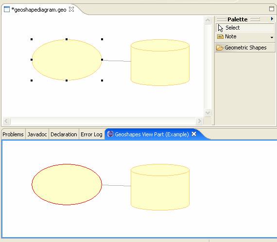
It is possible to view the same notation data
in 2 different viewers.
Since GEF / GMF implements the MFC design pattern, it is a simple
matter to view the same data in different viewers. The "Model" (Notation) is
the same in both viewers and synchronized with different "View"
(Figure) data through unique controllers (EditParts) in each viewer.
Creating a read-only
viewer of an existing diagram
If you wish to have a read-only view of the diagram, this is
probably well suited to be displayed in an Eclipse View instead of
a full-fledged editor.
In your implementation of the IViewPart the createPartControl would create the Viewer to
display the diagram.
The DiagramEditPart is retrieved and
explicitly set to disable the EditMode
capability. It is a
perquisite that a DiagramView object is
?in-hand?. This could
be retrieved by invoking an action from the Diagram element in the
Model Explorer.
// the assumption of this method is that the
DiagramView has been pre-loaded
private
GraphicalViewer viewer;
private
GraphicalViewer viewer;
public
class TraceDiagramGraphicalViewer extends DiagramGraphicalViewer {
// no
implementation. This class is extended
from
//
DiagramGraphicalViewer
for type
information only.
}
public
void createPartControl(Composite comp)
{
viewer = new TraceDiagramGraphicalViewer();
viewer.createControl
(comp);
viewer.getControl
().setBackground(ColorConstants.listBackground);
DiagramEditDomain editDomain = new
DiagramEditDomain
(null);
editDomain.setCommandStack
(new DiagramCommandStack(editDomain));
viewer.setEditDomain
(
editDomain);
viewer.setRootEditPart
(new DiagramRootEditPart());
viewer.setEditPartFactory
(
EditPartService.getInstance());
viewer.setContents
(GeoDiagramEditor.diagView));
viewer.flush
();
// now disable
editing
Assert.isTrue
(
viewer.getContents() instanceof DiagramEditPart);
DiagramEditPart diagEP = (DiagramEditPart)
viewer.getContents
();
diagEP.disableEditMode
();
How
to change the color of
a shape dynamically
[
back to top]
In the example
#Creating a
read-only viewer of an existing diagram it is necessary to
create a new GraphicalViewer class
(TraceDiagramGraphicalViewer) for the
type information to distinguish EditParts hosted in a regular editor vs. a
custom Viewer to allow for animation. Changing the colors of
individual EditParts can be achieved
dynamically by installing an EditPolicy
on the EditParts condition on them
being owned by the new Viewer class above.
The EditPolicy will then listen to the
appropriate condition and change the color of the EditPart's figures accordingly.
First we need to define an EditPolicyProvider that will install this new
editpolicy. The Extension code in the
plugin.xml would look something like
the following:
<extension
id
=
"TraceEditPolicyProvider"
name
=
"TraceEditPolicyProvider"
point
=
"org.eclipse.gmf.runtime.diagram.ui.editpolicyProviders"
>
<editpolicyProvider
class
=
"<package namespace>.TraceDiagramEditPolicyProvider"
>
<Priority
name
=
"Low"
>
</Priority>
<object
class
=
"org.eclipse.gmf.runtime.diagram.ui.editparts.IGraphicalEditPart"
id
=
"TraceEditPart"
>
<method
name=
"
getViewer
()"
>
<
value class=
"
=
"<package
namespace>.TraceDiagramGraphicalViewer"
/>
</method>
</object>
<context
editparts
=
"TraceEditPart"
>
</context>
</editpolicyProvider>
</extension>
Finally, the EditPolicy class itself can be defined. In this particular example,
we are adding a mouse listener the
allows us to trace mouse movement entering and exiting the
host EditPart. On entry, we color the
figure to red and on exit set it back to the original
color.
public
class TraceDiagramEditPolicy extends GraphicalEditPolicy {
private class TraceMouseMotionListener extends MouseMotionListener.Stub {
private Color color;
/**
* @see
com.ibm.etools.draw2d.MouseMotionListener#mouseEntered(
MouseEvent)
*/
public void mouseEntered(MouseEvent me) {
color = getHostFigure().getForegroundColor();
getHostFigure
().setForegroundColor(new Color(null, new
RGB(255, 0, 0)));
getHostFigure
().invalidate();
}
/**
* @see
com.ibm.etools.draw2d.MouseMotionListener#mouseExited(
MouseEvent)
*/
public void mouseExited(MouseEvent me) {
getHostFigure
().setForegroundColor(color);
getHostFigure
().invalidate();
}
}
/**
mouse motion listener for the owner shape and handles */
private TraceMouseMotionListener myMouseListener = new TraceMouseMotionListener();
/**
*
* @see org.eclipse.gef.EditPolicy#activate
()
*/
public void activate() {
super.activate
();
getHostFigure
().addMouseMotionListener(myMouseListener);
}
/**
*
* @see org.eclipse.gef.EditPolicy#deactivate
()
*/
public void deactivate() {
getHostFigure
().removeMouseMotionListener(myMouseListener);
super.deactivate
();
}
}
Shapes subclassed from ShapeEditPart are resizable by default.
The resizable editpolicy is
a special case in that it is installed via the LayoutEditPolicy on
the diagram in the routine createChildEditPolicy.
The GMF diagram layer has
it's own LayoutEditPolicy called
XYLayoutEditPolicy which calls inside createChildEditPolicy a
public method of ShapeEditPart called
getPrimaryDragEditPolicy.
The default implementation
returns a ResizableShapeEditPolicy which supports the drag resize
handles.
If the shape doesn't appear to be resizable, make sure that you're
not overriding the getPrimaryDragEditPolicy method in your EditPart
and / or set a breakpoint there to make sure it's returning the
ResizableShapeEditPolicy.
How do I make a
shape non-resizable?
Override the getPrimaryDragEditPolicy in your EditPart to return
the NonResizableEditPolicyEx
Example (in LEDEditPart):
/**
* @see
org.eclipse.gmf.runtime.diagram.ui.editparts.ShapeEditPart#getPrimaryDragEditPolicy()
*/
public EditPolicy
getPrimaryDragEditPolicy() {
return new
NonResizableEditPolicyEx();
}
Copyright
(c) 2000,2005 IBM Corporation and others. All Rights
Reserved.