Planning for Routers on Your Network
Recall that in TCP/IP, two types of entities exist on a network: hosts
and routers. All networks must have hosts, while not all networks require routers.
The physical topology of the network determines if you need routers. This section
introduces the concepts of network topology and routing. These concepts are important when
you decide to add another network to your existing network environment.
Network Topology Overview
Network topology describes how networks fit together. Routers are the entities that connect
networks to each other. A router is any machine that has two or
more network interfaces and implements IP forwarding. However, the system cannot function as
a router until properly configured, as described in Configuring an IPv4 Router.
Routers connect two or more networks to form larger internetworks. The routers must
be configured to pass packets between two adjacent networks. The routers also should
be able to pass packets to networks that lie beyond the adjacent networks.
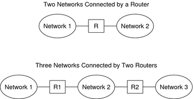
The following figure shows the basic parts of a network topology. The first
illustration shows a simple configuration of two networks that are connected by a
single router. The second illustration shows a configuration of three networks, interconnected by
two routers. In the first example, Router R joins Network 1 and Network
2 into a larger internetwork. In the second example, Router R1 connects Networks
1 and 2. Router R2 connects Networks 2 and 3. The connections form
a network that includes Networks 1, 2, and 3.
Figure 2-3 Basic Network Topology

In addition to joining networks into internetworks, routers route packets between networks that
are based on the addresses of the destination network. As internetworks grow more
complex, each router must make more and more decisions about the packet destinations.
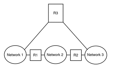
The following figure shows a more complex case. Router R3 directly connects networks
1 and 3. The redundancy improves reliability. If network 2 goes down, router
R3 still provides a route between networks 1 and 3. You can interconnect
many networks. However, the networks must use the same network protocols.
Figure 2-4 A Network Topology That Provides an Additional Path Between Networks

How Routers Transfer Packets
The IP address of the recipient, which is a part of the
packet header, determines how the packet is routed. If this address includes the network
number of the local network, the packet goes directly to the host with
that IP address. If the network number is not the local network,
the packet goes to the router on the local network.
Routers maintain routing information in routing tables. These tables contain the IP address of
the hosts and routers on the networks to which the router is connected.
The tables also contain pointers to these networks. When a router receives a
packet, the router checks its routing table to determine if the table lists
the destination address in the header. If the table does not contain the
destination address, the router forwards the packet to another router that is listed
in its routing table. Refer to Configuring an IPv4 Router for detailed information on routers.
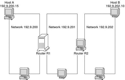
The following figure shows a network topology with three networks that are connected
by two routers.
Figure 2-5 A Network Topology With Three Interconnected Networks

Router R1 connects networks 192.9.200 and 192.9.201. Router R2 connects networks 192.9.201
and 192.9.202. If Host A on network 192.9.200 sends a message to
Host B on network 192.9.202, the following events occur:
Host A sends a packet out over network 192.9.200. The packet header contains the IPv4 address of the recipient Host B, 192.9.202.10.
None of the machines on network 192.9.200 has the IPv4 address 192.9.202.10. Therefore, Router R1 accepts the packet.
Router R1 examines its routing tables. No machine on network 192.9.201 has the address 192.9.202.10. However, the routing tables do list Router R2.
R1 then selects R2 as the “next hop” Router. R1 sends the packet to R2.
Because R2 connects network 192.9.201 to 192.9.202, R2 has routing information for Host B. Router R2 then forwards the packet to network 192.9.202, where Host B accepts the packet.
