Power Management Flow of Control
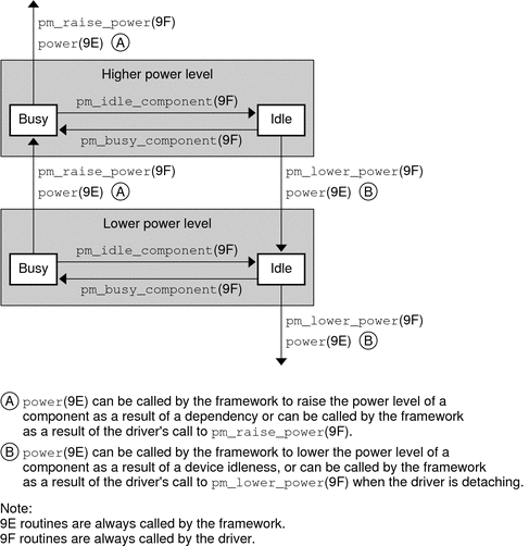
Figure 12-1 illustrates the flow of control in the power management framework.
When a component's activity is complete, a driver can call pm_idle_component(9F) to
mark the component as idle. When the component has been idle for
its threshold time, the framework can lower the power of the component to
its next lower level. The framework calls the power(9E) function to
set the component's power to the next lower supported power level, if a
lower level exists. The driver's power(9E) function should reject any attempt to lower
the power level of a component when that component is busy. The
power(9E) function should save any state that could be lost in a
transition to a lower level prior to making that transition.
When the component is needed at a higher level, the driver calls
pm_busy_component(9F). This call keeps the framework from lowering the power still further and
then calls pm_raise_power(9F) on the component. The framework next calls power(9E) to raise
the power of the component before the call to pm_raise_power(9F) returns.
The driver's power(9E) code must restore any state that was lost in the
lower level but that is needed in the higher level.
When a driver is detaching, the driver should call pm_lower_power(9F) for each component
to lower its power to its lowest level. The framework can then
call the driver's power(9E) routine to lower the power of the component before the
call to pm_lower_power(9F) returns.
Figure 12-1 Power Management Conceptual State Diagram

